
The logical Enterprise Architecture identifies the major systems and data flows required by the Enterprise indcluding computer operating Systems, application software, network device configuration, and protocols. It should addresses all Enterprise Levels from Plant Control to Corporate Finance.
A "logical Architecture Diagram" shows the relationship of Software Systems and Applications and the data flows between them. This is accomplished during the Conceptual Engineering Phase of a project, (or the Master Planning Phase of a new corporate program or enterprise). This is done before the computers and networks that these systems will run on are considered.
This Logical Architecture diagram indicates the boundary of "Plant Wide Systms" that form the interface between Plant and Corporate IT systems. This is the interface described in ISA 95 (for Process Industries) including B2PML (Business to Process Markup language).
Interfaces between major systems are also indicated, such as between Process Operation Systems, and Plant Manufacturing Management Systems. This interface at the top of the "Process Operations" architecture is where the Plant Firewall and the Process Data Historian is usually located, and it is the boundary where the CIA (Confidentiality, Integrity, Availability) priorities of IT systems change to the SAIC (Safety, Availability, Integrity, Confidenciality) priorities of Plant Automation and Control Systems (ACS). This is also where the IT "Zero Trust" cybersecurity environment changes to a "Managed Trust" ACS environment.
Note that interfaces between other major plant "Zones" like Engineering or the Quality Laboratory may also be required, and these should be protected by "gateways" and/or protocol converters.
This diagram also shows Logical Interfaces with Engineering, Laboratory and other Plant Systems.
The interfaces shown above are accomplished by logical data flows between systems that flow through physical networks and computers. It is possible to design flat logical networks implemented within segmented physical networks. It is also possible to design segmented logical networks implemented within flat physical networks (e.g. 5G cellular). Neither approach by itself is likely to be optimal.
Good design involves evaluation of data-flows in the form of "data-flow diagrams". An conceptual example is shown in Figure 2.
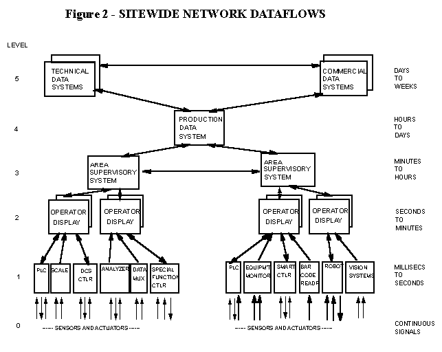
Application programs must be positioned at the appropriate level in the information architecture to satisfy the 4Rs (Response, Resolution, Reliability, and Resilience) requirements of the application.
The positioning of applications may depend on that plant and site. It is possible that a given application might exist at level 3 in one plant, and at level 4 or 5 in another. Also, many applications span several levels. Possible "multi-level" examples include quality management, production reporting, material tracking, and maintenance.
Clearly, several different applications operating at different levels may require access to the same piece of production information (eg. input flow rate). It is not practical to have each system independently request this piece of data from the level 1 device to which the sensor is connected.
In most cases, access of data is primarily from an application which is one level higher in the architecture. However, this is not always the case. For example, a level 5 engineering system may require one minute averages (Level 2) for the purpose of process unit studies. Similarly, Level 5 cost information may be provided to Level 2 or 3 optimization algorithms. None-the-less, inquiries spanning more than one level are the exception, and in general the network should be designed to optimize communications between adjacent Levels.
As data moves up through the architecture, it tends to become increasingly summarized. It also concentrates from many devices and data highways at the lowest levels, to a single production database at level 4. This Level 4 system also provides the "gateway" through which the "office systems" view the plant data, and through which plant systems view "office" information. Interestingly, as data moves up from Level 4, it tends to "fan out" again, into various commercial and technical systems. The Level 4 Database is therefore a "nexus" for all data moving from, or to, the operations level.
Once the data flow requirements are established, it is necessary to implement this within a the logical architecture of that enterprise. The logical architecture need not always have the same number of architectural levels as the physical architecture (although this is usually the case "below the plant firewall"
A principal difference in the appearance of the Sitewide Network and the Network Dataflows results from the ability of modern networks to allow any device on the highway to communicate directly with any other device. For example, it is possible for a Level 4 "Sitewide Database" to get data from a Level 3 Supervisory computer. However a Level 3 system may exchange data directly with another Level 3 supervisory system.
Communications in the network may range from 4-20 milliamp analog signals to high speed co-axial or optical highways. Each of these kinds of connections has a role, and indeed also has its own messages in terms of impact on the Response, Resolution, Reliability, and Resilience of that part of the network.
Discretionary programming makes possible integration of communications protocols from different vendor's proprietary networks. Typically, a single Level 3 Processor may integrate information from several lower level devices or networks.
These operating systems, such as Windows, Unix, and others, provide an environment which can support the full 7-Level OSI/ISO communications model.
Sitewide Networks may be implemented using:
For obvious commercial and technical reasons, control system vendors are very reluctant to allow users and other vendors to connect devices directly to their proprietary data highway(s).
For this and other reasons, A "PROPRIETARY" NETWORK SHOULD NEVER BE USED AS THE PLANT WIDE INDUSTRIAL NETWORK. This network forms the foundation for a Plant Wide System and must be "open" to allow connection of a wide range of systems from various vendors.
Also, since a proprietary network may not be based on agreed, published standards, it will almost certainly "evolve" over time. As a result, even if an owner standardizes on a single vendor, he may probably still encounter long-term compatibility problems in expanding his system.
Working with an industry-standard network also maximizes the likelihood of being able to purchase device interfaces for any "3rd Party" equipment which may be acquired in the future.
One exception may be "Broadband Trunks" where "logically" separate channels may share "physical" transport media. However, the Broadband network must then operate at the Response, Reliability and Resilience level of the most critical industrial application that it carries.
Similarly, an Industrial LAN cannot afford to be "clogged" by large volumes of data processing information, such as would routinely be transferred on the Office LAN. Otherwise, critical control or alarm data might arrive too late.
The Office LAN typically has much lower response, reliability, and resilience requirements than the Industrial LAN. Industrial networks are often specified in such a way that "worst case" transmission delays of much less than a second can be guaranteed, whereas office LANs may sacrifice guaranteed response time for more efficient use of the available communications bandwidth. In the Industrial Network, failure of a single program or hardware interface to the highway must never "bring down" the whole network. However, elaborate precautions such as redundant data highways, are rarely justified in the office environment.
In many cases, a secure "gateway" is necessary between the two networks. This "gateway function" may be performed by the same processor as used to implement the Level 4 Site-Wide production Database, or it may be a separate processor.
This gateway performs several functions.
Since the "environments" for operation of an Office Network and an Industrial Network are so fundamentally different, protection is required between the networks. Commercial and Technical programmers on the Office LAN should not have to worry about possible consequences of their programming activities on the Industrial Network, or worse still on plant equipment!
Some data transfer between these levels is, however, essential. If optimization of the plant is to be accomplished, some cost information must be available to plant level systems. Similarly, production throughputs, losses and quality data, must be made available to "front office" systems. what is needed then is a "filter" which will allow certain kinds of pre-specified access.
Furthermore, it may be necessary to implement a "release" mechanism which will assure that production data is validated by supervision personnel before it is released to management information systems, and that cost information is verified before it is released for use by optimization algorithms at levels 3 and 4.