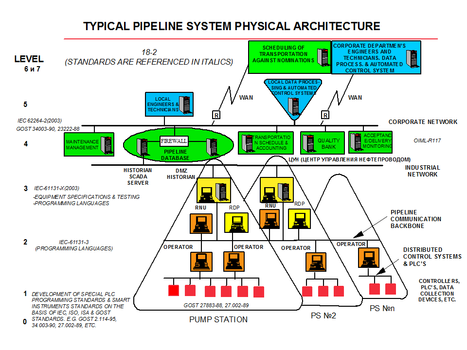
The following shows a typical Physical System Architecture diagram that might be developed during the Preliminary Engineering Phase for a process industry facility.
This Physical Network Architecture diagram indicates the interface with the Sitewide Industrial Network that forms the interface between Plant Control and Manufacturing Execution Systems (MES) . This is the interface described in ISA 95 (for Process Industries) including B2PML (Business to Process Markup language).
Interfacea between major systems are also indicated, such as between Process Control Systems, and Production Reporting and Scheduling Systems. This interface is where the "Plant Firewall" is usually located and it is the boundary where the CIA (Confidentiality, Integrity, Availability) priorities of IT systems change to the SAIC (Safety, Availability, Integrity, Confidentiality) priorities of Plant Automation and Control Systems (ACS). This is also where the "Managed Trust" ACS environment changes to the "Zero Trust" IT environment.
This diagram also shows Physical Interfaces with Quality Laboratory, Electronic Device Configuration, Engineering and other Plant Systems.
Thus, the Physical Enterprise Architecture Diagram and the Logical Enterprise Architecture Diagram parallel each other.
During the Preliminary Engineering Phase, a more detailed Physical Architecture Diagram is developed that defines both the "4R Criticality levels", and the separation by "Physical Units". These "units" may be process units (like Compression or Distillation units) or functional units like Quality Control laboratories or Engineering Offices.
Physical segregation by Network Level and Process Unit has been used in PERA to achieve "defense in depth" for many decades, and physical segregation is still the simplest and most effective method to improve the 4Rs. However, physical segregation is not the only way to protect different "Zones" in the Enterprise. In addition to physical segregation, most networks also allow "Logical Segregation". For example radio-frequency technologies like 5G cellular networks and Low Earth Orbit satellite networks provide a "physically flat" architecture that has been used to provide "campus" or even "regional" networks. These have the advantage of quick deployment and ease of modification. In this case, logical segregation is achieved through network configuration of routers, firewalls, etc. Logical segregation is, by its very nature, more vulnerable to attack, and is both complex to manage and prone to human errors.
Reliable and secure Plant control and inforamtion systems require a "Sitewide Network Architecture" (see "Process Industry Example in Figure 1). In the classical PERA architecture each process unit is separated into "levels", which are distinguished from each other by four principle criteria;
By contrast however, applications at level 5, can safely be shut down for hours or even days, with relatively minor consequences. Indeed, this is fortunate, since the communications, programming changes, and many users of these computers may make them more vulnerable to failure.
A key consideration for plant control and computing devices and the networks which connect them, is the ease with which these devices can be repaired after a hardware failure. For example, many continuous processes cannot easily be shut down to repair control devices such as PLC's (Programmable Logic Controllers) or DCS's (Distributed Control Systems). These devices and the networks connecting them must be maintainable "hot", (e.g., changing boards with the power still applied), to avoid shutting down associated equipment. These requirements apply to control software as well as hardware. Reloading, reconfiguration, and software patching may be necessary with the systems "online".
In addition to quickly repairing hardware and software failures, we must consider whether plant systems can survive or quckly recover after a cyberxecurity attack. Programs in ROM (that cannot be changed), and backup copies of programs and operating data that may be quickly restored are similar to hardware or software repairs.
Together, the ability to recover from hardware and software failures, human operating errors and cyber-attacks are defined as "Resilience". Resilience is rated in terms of MTTR (Mean Time To Repair).
How many Physical Architecture Levels should there be ?
The following indicates the "Resolution" of data gathered for that level of a typical continuous process industry facility.
| Level 5 | "1 month" integrals are used for planning feedwater heater preventive maintenance inspections. |
| Level 4 | "1 hour" integrals are used for process unit performance calculations. |
| Level 3 | "1 minute" averages of the flow rate are used by a plant area optimizer or an alarm/trip system. |
| Level 2 | "1 to 5 second" samples are displayed on an Plant Operator HMI (Human-Machine Interface). |
| Level 1 | Twice per secon, process parameters are used by a Level 1 controller to adjust the position of a flow control valve. |
| Level 0 | Transmitters sense Temperature, Pressure, Flow, and other process parameters at the highest practical sample rates. |
Once the data flow requirements are established (see "Logical Enterprise Architectures"), it is necessary to implement these within the physical architecture. This architecture consists of physical network media (like wires, radio or fiber optics), network devices (like modems, routers, and firewalls) and computers (including HMIs, PLCs and Servers).
These operating systems, such as Windows, Unix, and others, provide an environment which can support the full 7-Level OSI/ISO communications model.
Sitewide Networks may be implemented using:
For obvious commercial and technical reasons, control system vendors are very reluctant to allow users and other vendors to connect devices directly to their proprietary data highway(s).
For this and other reasons, A "PROPRIETARY" NETWORK SHOULD NEVER BE USED AS THE PLANT WIDE INDUSTRIAL NETWORK. This network forms the foundation for a Plant Wide System and must be "open" to allow connection of a wide range of systems from various vendors.
Also, since a proprietary network may not be based on agreed, published standards, it will almost certainly "evolve" over time. As a result, even if an owner standardizes on a single vendor, he may probably still encounter long-term compatibility problems in expanding his system.
Working with an industry-standard network also maximizes the likelihood of being able to purchase device interfaces for any "3rd Party" equipment which may be acquired in the future.
One exception may be "Broadband Trunks" where "logically" separate channels may share "physical" transport media. However, the Broadband network must then operate at the Response, Reliability and Resilience level of the most critical industrial application that it carries.
Similarly, an Industrial LAN cannot afford to be "clogged" by large volumes of data processing information, such as would routinely be transferred on the Office LAN. Otherwise, critical control or alarm data might arrive too late.
The Office LAN typically has much lower response, reliability, and resilience requirements than the Industrial LAN. Industrial networks are often specified in such a way that "worst case" transmission delays of much less than a second can be guaranteed, whereas office LANs may sacrifice guaranteed response time for more efficient use of the available communications bandwidth. In the Industrial Network, failure of a single program or hardware interface to the highway must never "bring down" the whole network. However, elaborate precautions such as redundant data highways, are rarely justified in the office environment.
In many cases, a secure "gateway" is necessary between the two networks. This "gateway function" may be performed by the same processor as used to implement the Level 4 Site-Wide production Database, or it may be a separate processor.
This gateway performs several functions.
Since the "environments" for operation of an Office Network and an Industrial Network are so fundamentally different, protection is required between the networks. Commercial and Technical programmers on the Office LAN should not have to worry about possible consequences of their programming activities on the Industrial Network, or worse still on plant equipment!
Some data transfer between these levels is, however, essential. If optimization of the plant is to be accomplished, some cost information must be available to plant level systems. Similarly, production throughputs, losses and quality data, must be made available to "front office" systems. what is needed then is a "filter" which will allow certain kinds of pre-specified access.
Furthermore, it may be necessary to implement a "release" mechanism which will assure that production data is validated by supervision personnel before it is released to management information systems, and that cost information is verified before it is released for use by optimization algorithms at levels 3 and 4.